Thursday, November 22, 2012
Setting environment variables...
When setting environment variables there are different ways of setting them depending on whether you are using full version AutoCAD or AutoCAD LT. To set an environment variable in AutoCAD you use the command...USERSx. X represents numbers 1-5. With AutoCAD LT you have to use...setenv. There are different environment variables when using this command. A couple of them are StrPrefix, and StrSuffix. You can use these with the diesel macros from the last couple posts for automated numbering.

Wednesday, November 21, 2012
Diesel Sequential Numbering...Adding prefix to numbering
So, this is a continuation to the last post of the diesel automated numbering.
In this one, I am going to show you how to make it to where you can enter in an environment variable to create a prefix that will show at the beginning of your numbering.
Below is the Macro coding for what we are going to work with:
*^c^c_text;\;$M=$(getenv,StrPrefix)$M=$(+,$(
$M=$(+,
Now, what is being added to the macro is the following; $M=$(getenv,StrPrefix)
this coding is pulling the value that a user sets for the StrPrefix.
To establish this environment value follow the steps below:
1. on the command line; type in _setenv (then hit enter)
2. type in StrPrefix (then hit enter)
3. enter in the text variable that you are wanting to use for your prefix (then hit enter)
Now, with your user variables already set you can run the new command and you will have the established prefix showing up in your text.
In this one, I am going to show you how to make it to where you can enter in an environment variable to create a prefix that will show at the beginning of your numbering.
Below is the Macro coding for what we are going to work with:
*^c^c_text;\;$M=$(getenv,StrPrefix)$M=$(+,$(
$M=$(+,
Now, what is being added to the macro is the following; $M=$(getenv,StrPrefix)
this coding is pulling the value that a user sets for the StrPrefix.
To establish this environment value follow the steps below:
1. on the command line; type in _setenv (then hit enter)
2. type in StrPrefix (then hit enter)
3. enter in the text variable that you are wanting to use for your prefix (then hit enter)
Now, with your user variables already set you can run the new command and you will have the established prefix showing up in your text.
Diesel Macro Auto Increment Numbers...
I received a question the other day from some one wanting to know how to automate sequential numbering in AutoCAD LT. So, i thought that this would be a good topic to put out there because I am sure that others have wanted to know if this was possible as well.
Anyways...to the topic.
First, the Macro:
*^c^c_text;\;0;$M=$(+,$(
$M=$(+,
One thing that you have to remember is that before you run the command you must the USERR1, and USERR2.
USERR1 value is going to be your initial value (i.e...99 to start with 100)
Then your USERR2 value is the increment in which you are wanting to increase with each placement of text.
To set these values type userr1 into your command line and hit enter and then enter in the initial value
see pics below:


Once value is set for USERR1, press enter, and then repeat for USERR2.
Now that your starting and incremental value have been set you can run the command and start picking away.
*EDIT*
The above macro justified the text to bottom left; the below macro is modified to justify to middle center.
*^c^c_text;J;MC;\;0;$M=$(+,$(getvar,USERR1),$(getvar,USERR2));setvar;USERR1;
$M=$(+,$(getvar,USERR1),$(getvar,USERR2));
Anyways...to the topic.
First, the Macro:
*^c^c_text;\;0;$M=$(+,$(
$M=$(+,
One thing that you have to remember is that before you run the command you must the USERR1, and USERR2.
USERR1 value is going to be your initial value (i.e...99 to start with 100)
Then your USERR2 value is the increment in which you are wanting to increase with each placement of text.
To set these values type userr1 into your command line and hit enter and then enter in the initial value
see pics below:


Once value is set for USERR1, press enter, and then repeat for USERR2.
Now that your starting and incremental value have been set you can run the command and start picking away.
*EDIT*
The above macro justified the text to bottom left; the below macro is modified to justify to middle center.
*^c^c_text;J;MC;\;0;$M=$(+,$(getvar,USERR1),$(getvar,USERR2));setvar;USERR1;
$M=$(+,$(getvar,USERR1),$(getvar,USERR2));
Monday, November 19, 2012
building estimation forms (Inventor iLogic)...
Creating an Estimation form with Inventor iLogic and Excel...
To be able to create an estimation form and link it to information within your Inventor model is a huge time saver in my line of work. One thing that I have been working on is developing a form that will help our Project Managers estimate the cost of a project (at least structural steel wise) a little bit better, and quicker so that they can get initial bids out to customers quicker.
Below is a pic of the form that I have been creating:

and basically all the information but the added totals of everything is exported from an Inventor model. Below is another pic showing the iLogic forms that are built to supply this information that also control the construction of my model.

SyntaxEditor Code Snippet'
SyntaxEditor Code Snippet SyntaxEditor Code Snippet
To be able to create an estimation form and link it to information within your Inventor model is a huge time saver in my line of work. One thing that I have been working on is developing a form that will help our Project Managers estimate the cost of a project (at least structural steel wise) a little bit better, and quicker so that they can get initial bids out to customers quicker.
Below is a pic of the form that I have been creating:


Here is an example of how some of this is done...
'drafting hours and cost
GoExcel.CellValue("export.xls", "Sheet1", "A37")= drafting_hours
GoExcel.CellValue("export.xls", "Sheet1", "C37")= drafting_rate
'engineering cost and hours
GoExcel.CellValue("export.xls", "Sheet1", "A41")= engineering_hours
GoExcel.CellValue("export.xls", "Sheet1", "C41")= engineering_rate
'

'grating description and cost
GoExcel.CellValue("export.xls", "Sheet1", "A49")= grating_descrip
GoExcel.CellValue("export.xls", "Sheet1", "E49")= d126+1    'qty of 3ft wide panels
GoExcel.CellValue("export.xls", "Sheet1", "F49")= grating_cost
I have found that when you are attempting to export Bill of Material data out with a template that the template must be in a 97-2003 file format for it to work.
Wednesday, November 14, 2012
Using Inventor iLogic to help estimating...
One thing that I have come to realize about Inventor and the iLogic programming is that there are many things that it can be used for. One thing that I am working on developing with a company is an estimating program within inventor. This program has a standard tube frame built in an assembly and you can select from many different tube sizes whether it be square or rectangular and then in an iLogic form that was created you can enter in the cost for the tubing sizes and it will automatically calculate, and then there are other fields to add in shop hours, drafting hours, and engineering hours, and it will give you a total for those specific items and it totals the amount of steel that is in the assembly and adds that to the total of the other fields to give you an estimated cost.
As seen below in this pic...you can see the layout of how to define the frame structure, and then below that form is another one that defines the cost and weight.

Plus, once you have the basic information input and then the model rebuilds then you have your base structure that you can export.
As seen below in this pic...you can see the layout of how to define the frame structure, and then below that form is another one that defines the cost and weight.

Plus, once you have the basic information input and then the model rebuilds then you have your base structure that you can export.
Thursday, November 1, 2012
Controlling Beam sizes with iLogic...
Today I want to give an example of iLogic and one of the many ways that it can make designing easier.
First, is controlling Beam or frame sizes with the click of a button.

In iLogic you can write code that will manipulate the beams to allow you to select different sizes as shown below:
 Once programmed then you can go into your parameters and pulldown the list for your beam sizes.


First, is controlling Beam or frame sizes with the click of a button.
Here we have a I-beam frame
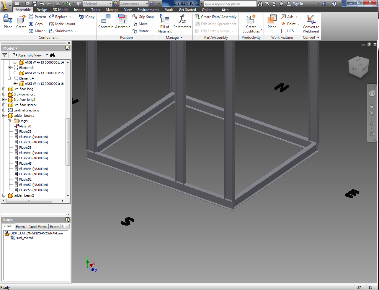
In iLogic you can write code that will manipulate the beams to allow you to select different sizes as shown below:


and then once you select one it will automatically update your assembly.

This is a very basic use for iLogic...one of the things that i am working on for this assembly is coding to be able to define which wall a ladder assembly will be placed and then having supporting beam members that are able to move around in the assembly depending on which wall is selected for the ladder.
So, as stated before...there are so many possiblities when it comes to using Inventor iLogic in your design process.
Inventor iLogic...is Awesome!
So, one of the programs that I enjoy using a lot is Inventor, and within Inventor is iLogic. If you want a way to reduce design time, get drawings out to the shop quicker and just make use of the program easier; then iLogic is the solution. For example, I am creating an iLogic program that will ease the structural design of modular skids for a company; it will reduce the actual structural design time by just inputing.
Below is a video showing an example of an iLogic program, that had a custom form imported into the program.
Below is a video showing an example of an iLogic program, that had a custom form imported into the program.
In the next post, I will give an example of some of the programming and how it works. If there are any questions out there about iLogic or even Inventor; I would be happy to answer any of them out there.
Subscribe to:
Posts (Atom)