There will be no more new posts on this blog after this one. We would like you to follow us to our new blog which is www.talkaboutcad.blogspot.com... We desire to share tips, tricks, new macros, or just general cadding information a couple times a week, so please visit our new blog frequently to see what is new!
Thank you!
Wednesday, August 28, 2013

Friday, August 2, 2013
Inventor Dynamic Simulation...
So last night I decided to mess around with Dynamic Simulation in Autodesk Inventor, and the video below is what I ended up with. I watched a video of someone simulating the motion of a trebuchet, so I decided that i was going to build a very basic catapult and see if I could get the simulation to work on it. So, below is my very basic catapult with the simulated arm motion and ball being thrown.
**fixed text visibility on the given background.
Thursday, August 1, 2013
Check out our Company Site!
Please visit our company site. On there you will find out who we are and what we do.
May be you have a project or some standard development task that you need to get complete, but don't have the time to. Fill out the contact us form and let us know what your project is and maybe we could help you out.
Also, if anyone has any technical questions dealing with AutoCAD, Inventor or SolidWorks we can help. Send us an email and then we can create a post on this blog covering the issue.
cadconsultingllc.weebly.com
Email address: cadconsultinginc@gmail.com
Thank you!
May be you have a project or some standard development task that you need to get complete, but don't have the time to. Fill out the contact us form and let us know what your project is and maybe we could help you out.
Also, if anyone has any technical questions dealing with AutoCAD, Inventor or SolidWorks we can help. Send us an email and then we can create a post on this blog covering the issue.
cadconsultingllc.weebly.com
Email address: cadconsultinginc@gmail.com
Thank you!
Tuesday, July 16, 2013
SaveAs Rule in Inventor ilogic
I use Inventor ilogic whenever possible, but one thing that has caused me problems is the fact that I couldn't save out a modified ilogic assembly without screwing up other drawings that were attached to that assembly...that is until now...
With the help from another blog; I was able to create a rule in ilogic that would perform a saveas off the assembly and then in turn would also run the rule under each part to create a brand new assembly and brand new parts within the assembly so that if you were to modify the main assembly this would not be affected by those changes.
Below is the code required for the saveas of an assembly:
'define the active document
oDoc = ThisDoc.Document
'create a file dialog box
Dim oFileDlg As inventor.FileDialog = Nothing
InventorVb.Application.CreateFileDialog(oFileDlg)

'check file type and set dialog filter
If oDoc.DocumentType = kPartDocumentObject Then
oFileDlg.Filter = "Autodesk Inventor Part Files (*.ipt)|*.ipt"
Else If oDoc.DocumentType = kAssemblyDocumentObject Then
oFileDlg.Filter = "Autodesk Inventor Assembly Files (*.iam)|*.iam"
Else If oDoc.DocumentType = kDrawingDocumentObject Then
oFileDlg.Filter = "Autodesk Inventor Drawing Files (*.idw)|*.idw"
End If

'set the directory to open the dialog at
oFileDlg.InitialDirectory = ThisDoc.WorkspacePath()
'set the file name string to use in the input box
oFileDlg.FileName = iProperties.Value("Project", "Project") & "_" & iProperties.Value("Summary", "Title")

'work with an error created by the user backing out of the save
oFileDlg.CancelError = True
On Error Resume Next
'specify the file dialog as a save dialog (rather than a open dialog)
oFileDlg.ShowSave()

'catch an empty string in the imput
If Err.Number <> 0 Then
MessageBox.Show("No File Saved.", "iLogic: Dialog Canceled")
ElseIf oFileDlg.FileName <> "" Then
MyFile = oFileDlg.FileName
'save the file
oDoc.SaveAs(MyFile, True) 'True = Save As Copy & False = Save As
End If
Now in my example; I have created a custom naming convention of the assembly that is controlled by the Project value, and the Title value within the iproperties. (shown below)
oFileDlg.FileName = iProperties.Value("Project", "Project") & "_" & iProperties.Value("Summary", "Title")
Now, to cause the parents under the assembly to saveas with predetermined values run the part rule within the assembly. (shown below)
iLogicVb.RunRule("2x4tube_1:1", "saveas")
When you run the rule it will automatically open a SaveAs dialog box for the assembly and once you hit save it will start running the SaveAs dialog for all the parts in the assembly that you call for the "RunRule".
Tuesday, March 12, 2013
Changing text style font with a Macro...
I know that one thing some people have problems with is when you xref or insert a title block into a drawing file; the text style changes back to the original font type. This was happening with the title block that our company is standardizing. So, I came up with a quick fix for our design group to take the standard text style and change the font type to the proper font so that the text would look the way it was meant to.
Here is the macro:
-STYLE;STANDARD;Arial Unicode MS;.125;;;;;
So, first in this code is obviously the command; which in this case is our text style command. Then you will list the text style that you are wanting to change; next will be the font style that you are wanting to change it to, and then finally the height of the text. Last there are a bunch of semi-colons attached to the end of the code to enter through other questions that comes with changing the text style, but none of them applied in this case.
Below is an example of this being used in one of my titleblock macros for inserting a title block and creating new layers for discipline specific drawings:
^C^C-STYLE;STANDARD;Arial Unicode MS;.125;;;;;ATTDIA;0;layout;set;layout1;
^C^C-insert;D-SIZE_BOTTOM(22X34)(REV_D);0,0;XYZ;1;1;1;0;;;;;;^C^C-INSERT;*REV-TEXT.DWG;0,0;1;0;^c^cpsetupin;"D_SIZE-PID.DWG" "*";
^c^c-plot;n;layout1;11x17;;n;y;n;
-LAYER;NEW;D_EQ;LTYPE;CONTINUOUS;D_EQ;LWEIGHT;.020;D_EQ;COLOR;11;D_EQ;;
-LAYER;NEW;D_PR;LTYPE;CONTINUOUS;D_PR;LWEIGHT;.030;D_PR;COLOR;14;D_PR;;
-LAYER;NEW;D_UT;LTYPE;CONTINUOUS;D_UT;LWEIGHT;.015;D_UT;COLOR;9;D_UT;;
-LAYER;NEW;D_FIT;LTYPE;CONTINUOUS;D_FIT;LWEIGHT;.015;D_FIT;COLOR;7;D_FIT;;
-LAYER;NEW;D_INST;LTYPE;CONTINUOUS;D_INST;LWEIGHT;.010;D_INST;COLOR;4;D_INST;;
-LAYER;NEW;D_FUT;LTYPE;PHANTOM;D_FUT;LWEIGHT;.010;D_FUT;COLOR;6;D_FUT;;
-LAYER;NEW;D_EXIST;LTYPE;DASHED;D_EXIST;LWEIGHT;.010;D_EXIST;COLOR;5;D_EXIST;;
-LAYER;NEW;D_TXT;LTYPE;CONTINUOUS;D_TXT;LWEIGHT;.015;D_TXT;COLOR;7;D_TXT;;
-LAYER;NEW;VIEWPORT;COLOR;211;VIEWPORT;PLOT;NO;VIEWPORT;;
^C^C_EATTEDIT;7.153207,1.737254,0.000000;^C^C-LA;SET;VIEWPORT;;^c^c-vports;1,21.4999;27.5,2;^C^C-LA;SET;D_PR;;^C^C_.INSERT;LOGO-CALLOUT;18.25,1.375,0;XYZ;1;1;1;0;-DIMSTYLE;R;EPIC;^C
Here is the macro:
-STYLE;STANDARD;Arial Unicode MS;.125;;;;;
So, first in this code is obviously the command; which in this case is our text style command. Then you will list the text style that you are wanting to change; next will be the font style that you are wanting to change it to, and then finally the height of the text. Last there are a bunch of semi-colons attached to the end of the code to enter through other questions that comes with changing the text style, but none of them applied in this case.
Below is an example of this being used in one of my titleblock macros for inserting a title block and creating new layers for discipline specific drawings:
^C^C-STYLE;STANDARD;Arial Unicode MS;.125;;;;;ATTDIA;0;layout;set;layout1;
^C^C-insert;D-SIZE_BOTTOM(22X34)(REV_D);0,0;XYZ;1;1;1;0;;;;;;^C^C-INSERT;*REV-TEXT.DWG;0,0;1;0;^c^cpsetupin;"D_SIZE-PID.DWG" "*";
^c^c-plot;n;layout1;11x17;;n;y;n;
-LAYER;NEW;D_EQ;LTYPE;CONTINUOUS;D_EQ;LWEIGHT;.020;D_EQ;COLOR;11;D_EQ;;
-LAYER;NEW;D_PR;LTYPE;CONTINUOUS;D_PR;LWEIGHT;.030;D_PR;COLOR;14;D_PR;;
-LAYER;NEW;D_UT;LTYPE;CONTINUOUS;D_UT;LWEIGHT;.015;D_UT;COLOR;9;D_UT;;
-LAYER;NEW;D_FIT;LTYPE;CONTINUOUS;D_FIT;LWEIGHT;.015;D_FIT;COLOR;7;D_FIT;;
-LAYER;NEW;D_INST;LTYPE;CONTINUOUS;D_INST;LWEIGHT;.010;D_INST;COLOR;4;D_INST;;
-LAYER;NEW;D_FUT;LTYPE;PHANTOM;D_FUT;LWEIGHT;.010;D_FUT;COLOR;6;D_FUT;;
-LAYER;NEW;D_EXIST;LTYPE;DASHED;D_EXIST;LWEIGHT;.010;D_EXIST;COLOR;5;D_EXIST;;
-LAYER;NEW;D_TXT;LTYPE;CONTINUOUS;D_TXT;LWEIGHT;.015;D_TXT;COLOR;7;D_TXT;;
-LAYER;NEW;VIEWPORT;COLOR;211;VIEWPORT;PLOT;NO;VIEWPORT;;
^C^C_EATTEDIT;7.153207,1.737254,0.000000;^C^C-LA;SET;VIEWPORT;;^c^c-vports;1,21.4999;27.5,2;^C^C-LA;SET;D_PR;;^C^C_.INSERT;LOGO-CALLOUT;18.25,1.375,0;XYZ;1;1;1;0;-DIMSTYLE;R;EPIC;^C
Monday, December 31, 2012
Excel and AutoCAD LT diesel macro...
Last week I had a question posed to me about linking an excel document to Autocad and then having a diesel macro that establishes a user variable and then returns that value to the excel document which in turn returns another variable to Autocad for labeling functionality. For instance if you were assigning names to office spaces and you had them all in an excel document. You could create a vlookup function in a cell, and have the cell that autocad will return a value to as the one that the vlookup is looking at to return your name.
The diesel macro establishes a user variable is the indexing number and another one as the incrementing number. Each time you use the command it will update one table which in turn updates the excel document and returns you the name that is associated with that number.
Is there anyone that has needed this function or any one who would like to have this function? If so, keep reading this post.


Now pick on that table and highlight cell “A1”…
Then on the ribbon panel you will see a button that says field…click that button.

See pic below on next page for clarification…
Once the expression is entered then click the okay button to get out of the dialog box. And then escape out of your table. If done right then the value in the cell should look like what is in the above picture…gray with white text.

Next is some of the tricky stuff.


We are going to go through the creating the datalink to the same excel doc but this time the linked range is going to be the one that is going to show the name in it.
When creating this datalink…I would recommend naming it “names2” just because that name is already built into the macro.
Now once you have that done you are basically ready to create the button with the macro…
Below is the macro for the button…
*^C^Cupdatefield;all;;tabledit;\;datalinkupdate;w;all;;-table;l;names2;\explode;$m=$(getvar,lastpoint);setvar;userr1;$m=$(+,$(getvar,userr1),$(getvar,userr2))
Once you place it you will notice that it has borders…and that is because it is inserted as a block and then explode in the macro. The border lines won’t print out on your drawing.
Again, we are using userr1, and userr2; so userr2 always stays as a value of 1.
Okay…I think that is it…at least I hope that is it.
Let me know if there is anything else that you need clarified and I will do my best to help clarify things.
The diesel macro establishes a user variable is the indexing number and another one as the incrementing number. Each time you use the command it will update one table which in turn updates the excel document and returns you the name that is associated with that number.
Is there anyone that has needed this function or any one who would like to have this function? If so, keep reading this post.
Alrighty…the instructions to
automating (fingers crossed) the names being inserted by table and then
exploded.
First up…creating a new table style:
In the command line type: tables
Then hit enter.
The following dialog box should come up.

Once you click the “New…” button enter whatever name you want to name
it.
In the next dialog box follow as shown in pic below

In the borders tab change the border to be “No Border”
Then hit okay.
Once done you will go back to the main dialog for the table styles.
Make sure that the current style set is the one that you just created.
Now comes is the fun part…
First…lets create a table that is (1) column x (1) row. And then insert
that into your drawing.Now pick on that table and highlight cell “A1”…
Then on the ribbon panel you will see a button that says field…click that button.

Then in the field dialog change your “Field category:” to show “Other”.
In the “Field names:” column pick “DieselExpression”.
And then in the box to the right enter the diesel expression that is
shown.See pic below on next page for clarification…
Once the expression is entered then click the okay button to get out of the dialog box. And then escape out of your table. If done right then the value in the cell should look like what is in the above picture…gray with white text.

Next is some of the tricky stuff.
Pick the table that you just created
And click on the link cell button as shown in picture below.
Then follow the steps that are shown below in pictures.

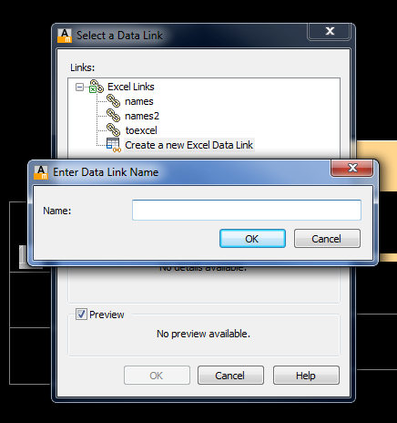

Here is where you will select the excel file with the names that you
are going to be generating in your cad file.

Be sure to select the “link to range” button and then put a random cell
in there that you can remember for later when you have to get into your excel
doc and create a vlookup value.
p.s. you have to do at least a 2 cell range or it won’t take it. Also, make the sheet a different one from
where the names are as well.
Now…we need to get into the excel file, and I am kind of hoping that
you have the names numbered 1-300 or something because it will make it a lot
easier, but if you have a different case of associating a number to names then leave a comment about what you are needing and I will see what I can do to help remedy the issue.
In the excel doc…on the sheet with the names; off to the right of those
columns pick an empty cell and create a vlookup…the “Sheet?!A!” is referring to
whatever sheet and cell you linked the table to that you have already created.
=vlookup(Sheet?!A1,A1:b300,2)
Make sure you save the excel doc and then close it…
Next…We are going to go through the creating the datalink to the same excel doc but this time the linked range is going to be the one that is going to show the name in it.
When creating this datalink…I would recommend naming it “names2” just because that name is already built into the macro.
Now once you have that done you are basically ready to create the button with the macro…
Below is the macro for the button…
*^C^Cupdatefield;all;;tabledit;\;datalinkupdate;w;all;;-table;l;names2;\explode;$m=$(getvar,lastpoint);setvar;userr1;$m=$(+,$(getvar,userr1),$(getvar,userr2))
It is amazing how short it is, and yet there is so much work prior to
being able to use it.
When you run the macro the first thing it will do is prompt you to pick
a table…and you will pick the initial table that you built that has the
updating variable number. Once you pick
it then the next thing you do is place the name.Once you place it you will notice that it has borders…and that is because it is inserted as a block and then explode in the macro. The border lines won’t print out on your drawing.
Again, we are using userr1, and userr2; so userr2 always stays as a value of 1.
Okay…I think that is it…at least I hope that is it.
Let me know if there is anything else that you need clarified and I will do my best to help clarify things.
Thursday, December 20, 2012
Instrumentation symbols with automated numbers...(diesel macro)
Working in the Process and Mechanical field you come across a lot of things that need to be automated so that it makes things a little easier on you as a designer. So, one of the latest Diesel macros that I wrote is for automated ISA Instrumentation symbols. The good thing is that this code can be used to create user commands for all instrumentation symbols and it will flow seamlessly with each symbol placed.
Okay, now to the code...
*^c^c$M=$(+,$(getvar,USERR1),$(getvar,USERR2));setvar;USERR1;
$M=$(+,$(getvar,USERR1),$(getvar,USERR2));-insert;
DISCRETE-PRIMARY;\1;1;\$(GETVAR,USERR1);LIT;;;
The first portion of the code prior to the insert command is doing the math to increment the variables in the symbol. In this example you can see that we are using USERR1 & USERR2; where USERR1 is the initial number that you want to use, and then USERR2 is the variable that increases the value of USERR1.
The coding for the insert command may vary, but for mine after I call the symbol name I have a \1;1;\. This is the order of that bit of code...insertion point, scale x-coordinate, scale y-coordinate, rotation.
Once you go through that then the first attribute that is being filled in is the number; so, we tell it to get the USERR1 variable, and then the next one you can leave it as a user input by substituting "LIT" with "\". Then depending on how many other attributes you have attached to the symbol you will need a semicolon for each attribute after the "LIT" for it to be able to repeat the command properly.
Okay, now to the code...
*^c^c$M=$(+,$(getvar,USERR1),$(getvar,USERR2));setvar;USERR1;
$M=$(+,$(getvar,USERR1),$(getvar,USERR2));-insert;
DISCRETE-PRIMARY;\1;1;\$(GETVAR,USERR1);LIT;;;
The first portion of the code prior to the insert command is doing the math to increment the variables in the symbol. In this example you can see that we are using USERR1 & USERR2; where USERR1 is the initial number that you want to use, and then USERR2 is the variable that increases the value of USERR1.
The coding for the insert command may vary, but for mine after I call the symbol name I have a \1;1;\. This is the order of that bit of code...insertion point, scale x-coordinate, scale y-coordinate, rotation.
Once you go through that then the first attribute that is being filled in is the number; so, we tell it to get the USERR1 variable, and then the next one you can leave it as a user input by substituting "LIT" with "\". Then depending on how many other attributes you have attached to the symbol you will need a semicolon for each attribute after the "LIT" for it to be able to repeat the command properly.
Wednesday, December 5, 2012
Printing DataGridView's in VB...
Lately I have been writing a lot of selection and list programs, and one that I have written was for engineers to list out valves, control valves, and equipment for projects to be able to send them out for quoting and design purposes. One issue that I ran into was being able to get the DataGridView to print each line that is entered into the grid. But, I was able to find a bit of code and with a few modifications of my own...I was able to get it to print all lines entered into the grid, and also allow the programmer to change location of the grid on the printdocument file.
So, below is the code for the datagridview:
Dim mRow As Integer = 0
Dim newpage As Boolean = True
Private Sub PrintDocument1_PrintPage(sender As System.Object, e As System.Drawing.Printing.PrintPageEventArgs) Handles PrintDocument1.PrintPage
Dim tmpSize As New SizeF()
Dim tmpFont As Font
For i As Integer = 0 To DataGridView1.Columns.Count()
tmpFont = DataGridView1.ColumnHeadersDefaultCellStyle.Font
If tmpFont Is Nothing Then
tmpFont = DataGridView1.DefaultCellStyle.Font
End If
For j As Integer = 0 To DataGridView1.Rows.Count - 1
tmpFont = DataGridView1.Rows(j).DefaultCellStyle.Font
If tmpFont Is Nothing Then
tmpFont = DataGridView1.DefaultCellStyle.Font
End If
Next
Next
Dim cellsPerRow As New List(Of Integer)
Dim rowHeight As Integer = DataGridView1.ColumnHeadersHeight + DataGridView1.Rows(0).Height
Dim cellWidths(DataGridView1.Columns.Count - 1) As Integer
Dim rowWidths As New List(Of Integer)
Dim cellCounter As Integer = 0
With DataGridView1
Dim fmt As StringFormat = New StringFormat(StringFormatFlags.LineLimit)
fmt.LineAlignment =
StringAlignment.Center fmt.Trimming =
StringTrimming.EllipsisCharacter Dim y As Single = e.MarginBounds.Top + 120
Do While mRow < .RowCount
Dim row As DataGridViewRow = .Rows(mRow)
Dim x As Single = e.MarginBounds.Left
Dim h As Single = 0
For Each cell As DataGridViewCell In row.Cells
Dim rc As RectangleF = New RectangleF(x, y, cell.Size.Width, cell.Size.Height)
e.Graphics.DrawRectangle(Pens.Black, rc.Left, rc.Top, rc.Width, rc.Height)
If (newpage) Then
e.Graphics.DrawString(DataGridView1.Columns(cell.ColumnIndex).HeaderText, .Font,
Brushes.Black, rc, fmt)
Else
e.Graphics.DrawString(DataGridView1.Rows(cell.RowIndex - 1).Cells(cell.ColumnIndex).FormattedValue.ToString(), .Font, Brushes.Black, rc, fmt)
End If
x += rc.Width
h =
Math.Max(h, rc.Height) Next
newpage =
False y += h
mRow += 1
If y + h > e.MarginBounds.Bottom Then
e.HasMorePages =
True mRow -= 1
newpage =
True Exit Sub
End If
Loop
mRow = 0
End With
End Sub
So, the bit of code that is highlighted in yellow is where you can control the vertical location of the grid on the printdocument. Also if you want to change the location of the grid horizontally then; three lines below "dim y" there is the code line for the "dim x as single" you can change the value of that to change the horizontal location of the grid.
Happy Coding!
So, below is the code for the datagridview:
Dim mRow As Integer = 0
Dim newpage As Boolean = True
Private Sub PrintDocument1_PrintPage(sender As System.Object, e As System.Drawing.Printing.PrintPageEventArgs) Handles PrintDocument1.PrintPage
Dim tmpSize As New SizeF()
Dim tmpFont As Font
For i As Integer = 0 To DataGridView1.Columns.Count()
tmpFont = DataGridView1.ColumnHeadersDefaultCellStyle.Font
If tmpFont Is Nothing Then
tmpFont = DataGridView1.DefaultCellStyle.Font
End If
For j As Integer = 0 To DataGridView1.Rows.Count - 1
tmpFont = DataGridView1.Rows(j).DefaultCellStyle.Font
If tmpFont Is Nothing Then
tmpFont = DataGridView1.DefaultCellStyle.Font
End If
Next
Next
Dim cellsPerRow As New List(Of Integer)
Dim rowHeight As Integer = DataGridView1.ColumnHeadersHeight + DataGridView1.Rows(0).Height
Dim cellWidths(DataGridView1.Columns.Count - 1) As Integer
Dim rowWidths As New List(Of Integer)
Dim cellCounter As Integer = 0
With DataGridView1
Dim fmt As StringFormat = New StringFormat(StringFormatFlags.LineLimit)
fmt.LineAlignment =
StringAlignment.Center fmt.Trimming =
StringTrimming.EllipsisCharacter Dim y As Single = e.MarginBounds.Top + 120
Do While mRow < .RowCount
Dim row As DataGridViewRow = .Rows(mRow)
Dim x As Single = e.MarginBounds.Left
Dim h As Single = 0
For Each cell As DataGridViewCell In row.Cells
Dim rc As RectangleF = New RectangleF(x, y, cell.Size.Width, cell.Size.Height)
e.Graphics.DrawRectangle(Pens.Black, rc.Left, rc.Top, rc.Width, rc.Height)
If (newpage) Then
e.Graphics.DrawString(DataGridView1.Columns(cell.ColumnIndex).HeaderText, .Font,
Brushes.Black, rc, fmt)
Else
e.Graphics.DrawString(DataGridView1.Rows(cell.RowIndex - 1).Cells(cell.ColumnIndex).FormattedValue.ToString(), .Font, Brushes.Black, rc, fmt)
End If
x += rc.Width
h =
Math.Max(h, rc.Height) Next
newpage =
False y += h
mRow += 1
If y + h > e.MarginBounds.Bottom Then
e.HasMorePages =
True mRow -= 1
newpage =
True Exit Sub
End If
Loop
mRow = 0
End With
End Sub
So, the bit of code that is highlighted in yellow is where you can control the vertical location of the grid on the printdocument. Also if you want to change the location of the grid horizontally then; three lines below "dim y" there is the code line for the "dim x as single" you can change the value of that to change the horizontal location of the grid.
Happy Coding!
Wednesday, November 28, 2012
Dim extension lines set to center linetype...
So, I asked one of the guys that I work with about macros that he would want in AutoCAD to make things easier. And one of the things that he said would be nice is if you could write a macro that would change the extension line of the placed dimension to center linetype.
I had never heard of this being used, but I took the task on. What I found is that there are two ways to do this.
The first way is:
*^c^c-dimstyle;r;;_dimlinear;
Now the dimstyle that is used has the extension lines set to center linetype.
Now the other way to do this is:
*^c^cdimltex1;center;dimltec2;center;_dimlinear;-dimstyle;r;standard;
This just overrides the standard style to make the extension lines center linetype and then at the end we restore the original standard dimstyle.
So, if this is something that you do then. Hopefully this is something that helps you.
I had never heard of this being used, but I took the task on. What I found is that there are two ways to do this.
The first way is:
*^c^c-dimstyle;r;
Now the dimstyle that is used has the extension lines set to center linetype.
Now the other way to do this is:
*^c^cdimltex1;center;dimltec2;center;_dimlinear;-dimstyle;r;standard;
This just overrides the standard style to make the extension lines center linetype and then at the end we restore the original standard dimstyle.
So, if this is something that you do then. Hopefully this is something that helps you.
Tuesday, November 27, 2012
Letter automation...explained a little...
*^C^C_text;\;$m=$(if, $(<=,$(getvar,userr1),7),$(nth,$(getvar,userr1), A, B, C, D, E, F, G, H),$(if,$(>=,$(getvar,userr1),8),$(nth,$(getvar,userr3), I, J, K, L, M, N, O, P)),)$(if,$(>=,$(getvar,userr1),15),$(nth,$(getvar,userr4), Q, R, S, T, U, V, W, X),)$(if,$(>=,$(getvar,userr1),23),$(nth,$(getvar,userr5), Y, Z, AA, AB, AC, AD, AE, AF),);setvar;userr1;$M=$(+,$(getvar,USERR1),$(getvar,USERR2));setvar;userr3;
$M=$(+,$(getvar,USERR3),$(getvar,USERR2));
userr4;$M=$(+,$(getvar,USERR4),$(getvar,USERR2));
userr5;$M=$(+,$(getvar,USERR5),$(getvar,USERR2));
SETVAR;USERR3;\SETVAR;USERR4;\SETVAR;USERR5;\
So, above is the code that I had posted earlier for a somewhat automated lettering macro.
Now, I am going to explain how it works. First, we know that you start with the text command and go through all the prompts for it.
Then we work our way into the diesel portion of the macro...so, when developing this I found out that when using the "nth" function by itself you were limited to 7 arguments within the function.
Hence, why I embedded the "nth" function within multiple if statements.
Let's dissect these if statements a little:
$m=$(if, $(<=,$(getvar,userr1),7),$(nth,$(getvar,userr1), A, B, C, D, E, F, G, H),$(if,$(>=,$(getvar,userr1),8),$(nth,$(getvar,userr3), I, J, K, L, M, N, O, P)),)
so, in this first "if statement" I am telling it to evaluate the value of userr1.
$m=$(if, $(<=,$(getvar,userr1),7),$(nth,$(getvar,userr1), A, B, C, D, E, F, G, H),$(if,$(>=,$(getvar,userr1),8),$(nth,$(getvar,userr3), I, J, K, L, M, N, O, P)),)
If a value of 7 or less is returned then it moves on to this nth function where i am again calling for the value of userr1.
$m=$(if, $(<=,$(getvar,userr1),7),$(nth,$(getvar,userr1), A, B, C, D, E, F, G, H),$(if,$(>=,$(getvar,userr1),8),$(nth,$(getvar,userr3), I, J, K, L, M, N, O, P)),)
you will find a recurring theme throughout these if statements that we are evaluating the value of userr1...here we are looking to see if the value of userr1 is greater than or equal to 8.
$m=$(if, $(<=,$(getvar,userr1),7),$(nth,$(getvar,userr1), A, B, C, D, E, F, G, H),$(if,$(>=,$(getvar,userr1),8),$(nth,$(getvar,userr3), I, J, K, L, M, N, O, P)),)
If it returns a value of 8 or greater then it will move on to the next nth statement where we call for the value of userr3.
And this process repeats 2 more times with userr4, and userr5. One thing that you should notice is that the value to be returned from userr1 increase by a value of 8 with each "if statement".
Now that we are done with the if statements we can move on to the easier portions of the macro...how the values of the userr variables increase with each repetition of the command.
setvar;userr1;$M=$(+,$(getvar,USERR1),$(getvar,USERR2))
This code will be repeated four times...you will just have to copy and paste and then replace userr1 with userr3, userr4 or userr5.
And then the prompting for user input of the userr variables finishes out the macro.
Hope that this helped to clarify the process of the macro.
$M=$(+,$(getvar,USERR3),$(getvar,USERR2));
userr4;$M=$(+,$(getvar,USERR4),$(getvar,USERR2));
userr5;$M=$(+,$(getvar,USERR5),$(getvar,USERR2));
SETVAR;USERR3;\SETVAR;USERR4;\SETVAR;USERR5;\
So, above is the code that I had posted earlier for a somewhat automated lettering macro.
Now, I am going to explain how it works. First, we know that you start with the text command and go through all the prompts for it.
Then we work our way into the diesel portion of the macro...so, when developing this I found out that when using the "nth" function by itself you were limited to 7 arguments within the function.
Hence, why I embedded the "nth" function within multiple if statements.
Let's dissect these if statements a little:
$m=$(if, $(<=,$(getvar,userr1),7),$(nth,$(getvar,userr1), A, B, C, D, E, F, G, H),$(if,$(>=,$(getvar,userr1),8),$(nth,$(getvar,userr3), I, J, K, L, M, N, O, P)),)
so, in this first "if statement" I am telling it to evaluate the value of userr1.
$m=$(if, $(<=,$(getvar,userr1),7),$(nth,$(getvar,userr1), A, B, C, D, E, F, G, H),$(if,$(>=,$(getvar,userr1),8),$(nth,$(getvar,userr3), I, J, K, L, M, N, O, P)),)
If a value of 7 or less is returned then it moves on to this nth function where i am again calling for the value of userr1.
$m=$(if, $(<=,$(getvar,userr1),7),$(nth,$(getvar,userr1), A, B, C, D, E, F, G, H),$(if,$(>=,$(getvar,userr1),8),$(nth,$(getvar,userr3), I, J, K, L, M, N, O, P)),)
you will find a recurring theme throughout these if statements that we are evaluating the value of userr1...here we are looking to see if the value of userr1 is greater than or equal to 8.
$m=$(if, $(<=,$(getvar,userr1),7),$(nth,$(getvar,userr1), A, B, C, D, E, F, G, H),$(if,$(>=,$(getvar,userr1),8),$(nth,$(getvar,userr3), I, J, K, L, M, N, O, P)),)
If it returns a value of 8 or greater then it will move on to the next nth statement where we call for the value of userr3.
And this process repeats 2 more times with userr4, and userr5. One thing that you should notice is that the value to be returned from userr1 increase by a value of 8 with each "if statement".
Now that we are done with the if statements we can move on to the easier portions of the macro...how the values of the userr variables increase with each repetition of the command.
setvar;userr1;$M=$(+,$(getvar,USERR1),$(getvar,USERR2))
This code will be repeated four times...you will just have to copy and paste and then replace userr1 with userr3, userr4 or userr5.
And then the prompting for user input of the userr variables finishes out the macro.
Hope that this helped to clarify the process of the macro.
Somewhat automated lettering...(diesel macro)
I built this macro this morning upon a challenge issued to me yesterday.
To those who would like some way to automate lettering in AutoCAD LT...here is a Diesel Macro for LT that will allow you to atleast automate up to "AF":
*^C^C_text;\;$m=$(if, $(<=,$(getvar,userr1),7),$(nth,$(getvar,userr1), A, B, C, D, E, F, G, H),$(if,$(>=,$(getvar,userr1),8),$(nth,$(getvar,userr3), I, J, K, L, M, N, O, P)),)$(if,$(>=,$(getvar,userr1),15),$(nth,$(getvar,userr4), Q, R, S, T, U, V, W, X),)$(if,$(>=,$(getvar,userr1),23),$(nth,$(getvar,userr5), Y, Z, AA, AB, AC, AD, AE, AF),);setvar;userr1;$M=$(+,$(getvar,USERR1),$(getvar,USERR2));setvar;userr3;
$M=$(+,$(getvar,USERR3),$(getvar,USERR2));
userr4;$M=$(+,$(getvar,USERR4),$(getvar,USERR2));
userr5;$M=$(+,$(getvar,USERR5),$(getvar,USERR2));
SETVAR;USERR3;\SETVAR;USERR4;\SETVAR;USERR5;\
This macro requires more input on the users part than the number automation, but it works for a small amount of lettering.
Before you run the command for the first time you need to make sure that your userr1 is set to a value of 0, and that your userr2 is set to a value of 1 (which is for the incrementing).
When you run the command and you place the first letter; you will notice that it prompts you for the userr3, userr4, and userr5 values...just enter through these for now because you won't mess with them until a little further on.
Now, one thing that you need to keep in mind is the letters that are associated with which userr variable:
To those who would like some way to automate lettering in AutoCAD LT...here is a Diesel Macro for LT that will allow you to atleast automate up to "AF":
*^C^C_text;\;$m=$(if, $(<=,$(getvar,userr1),7),$(nth,$(getvar,userr1), A, B, C, D, E, F, G, H),$(if,$(>=,$(getvar,userr1),8),$(nth,$(getvar,userr3), I, J, K, L, M, N, O, P)),)$(if,$(>=,$(getvar,userr1),15),$(nth,$(getvar,userr4), Q, R, S, T, U, V, W, X),)$(if,$(>=,$(getvar,userr1),23),$(nth,$(getvar,userr5), Y, Z, AA, AB, AC, AD, AE, AF),);setvar;userr1;$M=$(+,$(getvar,USERR1),$(getvar,USERR2));setvar;userr3;
$M=$(+,$(getvar,USERR3),$(getvar,USERR2));
userr4;$M=$(+,$(getvar,USERR4),$(getvar,USERR2));
userr5;$M=$(+,$(getvar,USERR5),$(getvar,USERR2));
SETVAR;USERR3;\SETVAR;USERR4;\SETVAR;USERR5;\
This macro requires more input on the users part than the number automation, but it works for a small amount of lettering.
Before you run the command for the first time you need to make sure that your userr1 is set to a value of 0, and that your userr2 is set to a value of 1 (which is for the incrementing).
When you run the command and you place the first letter; you will notice that it prompts you for the userr3, userr4, and userr5 values...just enter through these for now because you won't mess with them until a little further on.
Now, one thing that you need to keep in mind is the letters that are associated with which userr variable:
userr1 - starts at A and ends with H
userr3 - starts at I and ends with P
userr4 - starts at Q and ends with X
userr5 - starts at Y and ends with AF
knowing this will help with understanding when to change variable values as you keep going up the alphabet. So, for example, once you place an "H"; when the prompt for userr3 appears change it to a value of 0. Once this is done you don't have to edit it anymore; you can just keep hitting enter through the variables until the end of that letter set on the userr variable.
On another note:
If you are a AutoCAD non-Lt user then the text command is a little different for you.
Instead of:
*^c^c_text;\;
You will have this:
*^c^c_text;\;;
And then if you want to add justification to it (for example...middle center justification)
*^c^c_text;j;mc;\;;
If anyone uses this macro and has issues please comment and let us know what changes you had to make to the macro.
Thank you for reading this post!
Monday, November 26, 2012
3 line date stamp...
Here is a quick and easy way to insert a textblock with username, date, and time.
^C^C_text;\;BY: $m=$(GETVAR,LOGINNAME);;;Date: $m=$(edtime,$(getvar,date),MO"/"dd"/"yy);;;Time: $m=$(edtime,$(getvar,date),HH:MMam/pm);
Yet again, this is another code for the AutoCAD LT users out there, but also works on Full version AutoCAD. The only difference for the non-LT users is that the beginning of the code is going to be as follows:
^c^c_text;j;mc;\;0;BY: $m=$(GETVAR,LOGINNAME);;;Date: $m=$(edtime,$(getvar,date),MO"/"dd"/"yy);;;Time: $m=$(edtime,$(getvar,date),HH:MMam/pm);
And then your finished product will be:

p.s. you won't have the line under the date...that is just my crosshair that got in the way...
^C^C_text;\;BY: $m=$(GETVAR,LOGINNAME);;;Date: $m=$(edtime,$(getvar,date),MO"/"dd"/"yy);;;Time: $m=$(edtime,$(getvar,date),HH:MMam/pm);
Yet again, this is another code for the AutoCAD LT users out there, but also works on Full version AutoCAD. The only difference for the non-LT users is that the beginning of the code is going to be as follows:
^c^c_text;j;mc;\;0;BY: $m=$(GETVAR,LOGINNAME);;;Date: $m=$(edtime,$(getvar,date),MO"/"dd"/"yy);;;Time: $m=$(edtime,$(getvar,date),HH:MMam/pm);
And then your finished product will be:

p.s. you won't have the line under the date...that is just my crosshair that got in the way...
Autocad macro...calling coordinate points on blocks
One thing that always comes up when creating P&ID's is; "how can you make it simplier to insert blocks and not have to take the time to do all the trimming of the lines once the block is in?"
I was actually able to create a couple of ways that allowed AutoCAD LT users and full version AutoCAD users to be able to do this. I have posted the LT version with the diesel macro, but today I am going to go over the lisp routine route.

Below you will see today's code that we are going to go over:
*^c^cattdia;0;^c^c_.insert;CHECK;\;1;\;;^C(setq edata (entget (setq en (entlast))));^c^cbreak;\f;(setq edata (entget (entnext (cdr (assoc -1 edata)))))(setq ip1 (cdr (assoc 10 edata)));(setq edata (entget (entnext (cdr (assoc -1 edata)))))(setq ip1 (cdr (assoc 10 edata)));^c^cattdia;1;^c
Okay...let's dive into this.
It isn't as overwhelming as it looks...it is actually quite simple.
So, first we are calling the attdia command and setting it to 0. We are doing this so that the 2 attributes that are attached to the block won't show up with a dialog prompt box.
Next we start the insert command and in this example we are inserting a check valve.
CHECK;\;1;\;; - the forward slash is to prompt for user input and this is for the insertion point.
CHECK;\;1;\;; - here we are telling it what scale the block is going to be inserted at.
CHECK;\;1;\;; - This is to set the rotation of the block...another user input prompt.
CHECK;\;1;\;; - and these last two semicolons are to enter through the 2 attributes that are attached to
the block.
Next, we will be going into the routine that recalls the block and calls for the point locations.
^C(setq edata (entget (setq en (entlast)))) - here we are telling AutoCAD to look up the last block that was inserted.
Now we call on the break command with the fence option.
^c^cbreak;\f;
Now comes the fun part of calling for the attribute points.
(setq edata (entget (entnext (cdr (assoc -1 edata)))))(setq ip1 (cdr (assoc 10 edata)));(setq edata (entget (entnext (cdr (assoc -1 edata)))))(setq ip1 (cdr (assoc 10 edata)));^c^cattdia;1;
For both points the code is the same, so once you type it once you will be able to copy and paste for the second point, and you can see that by the semicolon that has been made bold and underlined to help you see it.
But here is the code:
(setq edata (entget (entnext (cdr (assoc -1 edata)))))(setq ip1 (cdr (assoc 10 edata)))
the first (setq) grouping is calling for the bp1 attribute in the check valve block, and then the second (setq) grouping is what returns the coordinate values of the attribute, and then establishes the first point.
Now all you got to do is add a semicolon and then copy and paste the code for the second point and then end it with a semicolon and you are done.
Happy Trimming...
I was actually able to create a couple of ways that allowed AutoCAD LT users and full version AutoCAD users to be able to do this. I have posted the LT version with the diesel macro, but today I am going to go over the lisp routine route.

Below you will see today's code that we are going to go over:
*^c^cattdia;0;^c^c_.insert;CHECK;\;1;\;;^C(setq edata (entget (setq en (entlast))));^c^cbreak;\f;(setq edata (entget (entnext (cdr (assoc -1 edata)))))(setq ip1 (cdr (assoc 10 edata)));(setq edata (entget (entnext (cdr (assoc -1 edata)))))(setq ip1 (cdr (assoc 10 edata)));^c^cattdia;1;^c
Okay...let's dive into this.
It isn't as overwhelming as it looks...it is actually quite simple.
So, first we are calling the attdia command and setting it to 0. We are doing this so that the 2 attributes that are attached to the block won't show up with a dialog prompt box.
Next we start the insert command and in this example we are inserting a check valve.
CHECK;\;1;\;; - the forward slash is to prompt for user input and this is for the insertion point.
CHECK;\;1;\;; - here we are telling it what scale the block is going to be inserted at.
CHECK;\;1;\;; - This is to set the rotation of the block...another user input prompt.
CHECK;\;1;\;; - and these last two semicolons are to enter through the 2 attributes that are attached to
the block.
Next, we will be going into the routine that recalls the block and calls for the point locations.
^C(setq edata (entget (setq en (entlast)))) - here we are telling AutoCAD to look up the last block that was inserted.
Now we call on the break command with the fence option.
^c^cbreak;\f;
Now comes the fun part of calling for the attribute points.
(setq edata (entget (entnext (cdr (assoc -1 edata)))))(setq ip1 (cdr (assoc 10 edata)));(setq edata (entget (entnext (cdr (assoc -1 edata)))))(setq ip1 (cdr (assoc 10 edata)));^c^cattdia;1;
For both points the code is the same, so once you type it once you will be able to copy and paste for the second point, and you can see that by the semicolon that has been made bold and underlined to help you see it.
But here is the code:
(setq edata (entget (entnext (cdr (assoc -1 edata)))))(setq ip1 (cdr (assoc 10 edata)))
the first (setq) grouping is calling for the bp1 attribute in the check valve block, and then the second (setq) grouping is what returns the coordinate values of the attribute, and then establishes the first point.
Now all you got to do is add a semicolon and then copy and paste the code for the second point and then end it with a semicolon and you are done.
Happy Trimming...
Thursday, November 22, 2012
Setting environment variables...
When setting environment variables there are different ways of setting them depending on whether you are using full version AutoCAD or AutoCAD LT. To set an environment variable in AutoCAD you use the command...USERSx. X represents numbers 1-5. With AutoCAD LT you have to use...setenv. There are different environment variables when using this command. A couple of them are StrPrefix, and StrSuffix. You can use these with the diesel macros from the last couple posts for automated numbering.
Wednesday, November 21, 2012
Diesel Sequential Numbering...Adding prefix to numbering
So, this is a continuation to the last post of the diesel automated numbering.
In this one, I am going to show you how to make it to where you can enter in an environment variable to create a prefix that will show at the beginning of your numbering.
Below is the Macro coding for what we are going to work with:
*^c^c_text;\;$M=$(getenv,StrPrefix)$M=$(+,$(
$M=$(+,
Now, what is being added to the macro is the following; $M=$(getenv,StrPrefix)
this coding is pulling the value that a user sets for the StrPrefix.
To establish this environment value follow the steps below:
1. on the command line; type in _setenv (then hit enter)
2. type in StrPrefix (then hit enter)
3. enter in the text variable that you are wanting to use for your prefix (then hit enter)
Now, with your user variables already set you can run the new command and you will have the established prefix showing up in your text.
In this one, I am going to show you how to make it to where you can enter in an environment variable to create a prefix that will show at the beginning of your numbering.
Below is the Macro coding for what we are going to work with:
*^c^c_text;\;$M=$(getenv,StrPrefix)$M=$(+,$(
$M=$(+,
Now, what is being added to the macro is the following; $M=$(getenv,StrPrefix)
this coding is pulling the value that a user sets for the StrPrefix.
To establish this environment value follow the steps below:
1. on the command line; type in _setenv (then hit enter)
2. type in StrPrefix (then hit enter)
3. enter in the text variable that you are wanting to use for your prefix (then hit enter)
Now, with your user variables already set you can run the new command and you will have the established prefix showing up in your text.
Diesel Macro Auto Increment Numbers...
I received a question the other day from some one wanting to know how to automate sequential numbering in AutoCAD LT. So, i thought that this would be a good topic to put out there because I am sure that others have wanted to know if this was possible as well.
Anyways...to the topic.
First, the Macro:
*^c^c_text;\;0;$M=$(+,$(
$M=$(+,
One thing that you have to remember is that before you run the command you must the USERR1, and USERR2.
USERR1 value is going to be your initial value (i.e...99 to start with 100)
Then your USERR2 value is the increment in which you are wanting to increase with each placement of text.
To set these values type userr1 into your command line and hit enter and then enter in the initial value
see pics below:


Once value is set for USERR1, press enter, and then repeat for USERR2.
Now that your starting and incremental value have been set you can run the command and start picking away.
*EDIT*
The above macro justified the text to bottom left; the below macro is modified to justify to middle center.
*^c^c_text;J;MC;\;0;$M=$(+,$(getvar,USERR1),$(getvar,USERR2));setvar;USERR1;
$M=$(+,$(getvar,USERR1),$(getvar,USERR2));
Anyways...to the topic.
First, the Macro:
*^c^c_text;\;0;$M=$(+,$(
$M=$(+,
One thing that you have to remember is that before you run the command you must the USERR1, and USERR2.
USERR1 value is going to be your initial value (i.e...99 to start with 100)
Then your USERR2 value is the increment in which you are wanting to increase with each placement of text.
To set these values type userr1 into your command line and hit enter and then enter in the initial value
see pics below:


Once value is set for USERR1, press enter, and then repeat for USERR2.
Now that your starting and incremental value have been set you can run the command and start picking away.
*EDIT*
The above macro justified the text to bottom left; the below macro is modified to justify to middle center.
*^c^c_text;J;MC;\;0;$M=$(+,$(getvar,USERR1),$(getvar,USERR2));setvar;USERR1;
$M=$(+,$(getvar,USERR1),$(getvar,USERR2));
Monday, November 19, 2012
building estimation forms (Inventor iLogic)...
Creating an Estimation form with Inventor iLogic and Excel...
To be able to create an estimation form and link it to information within your Inventor model is a huge time saver in my line of work. One thing that I have been working on is developing a form that will help our Project Managers estimate the cost of a project (at least structural steel wise) a little bit better, and quicker so that they can get initial bids out to customers quicker.
Below is a pic of the form that I have been creating:

and basically all the information but the added totals of everything is exported from an Inventor model. Below is another pic showing the iLogic forms that are built to supply this information that also control the construction of my model.

SyntaxEditor Code Snippet'
SyntaxEditor Code Snippet SyntaxEditor Code Snippet
To be able to create an estimation form and link it to information within your Inventor model is a huge time saver in my line of work. One thing that I have been working on is developing a form that will help our Project Managers estimate the cost of a project (at least structural steel wise) a little bit better, and quicker so that they can get initial bids out to customers quicker.
Below is a pic of the form that I have been creating:


Here is an example of how some of this is done...
'drafting hours and cost
GoExcel.CellValue("export.xls", "Sheet1", "A37")= drafting_hours
GoExcel.CellValue("export.xls", "Sheet1", "C37")= drafting_rate
'engineering cost and hours
GoExcel.CellValue("export.xls", "Sheet1", "A41")= engineering_hours
GoExcel.CellValue("export.xls", "Sheet1", "C41")= engineering_rate
'

'grating description and cost
GoExcel.CellValue("export.xls", "Sheet1", "A49")= grating_descrip
GoExcel.CellValue("export.xls", "Sheet1", "E49")= d126+1    'qty of 3ft wide panels
GoExcel.CellValue("export.xls", "Sheet1", "F49")= grating_cost
I have found that when you are attempting to export Bill of Material data out with a template that the template must be in a 97-2003 file format for it to work.
Wednesday, November 14, 2012
Using Inventor iLogic to help estimating...
One thing that I have come to realize about Inventor and the iLogic programming is that there are many things that it can be used for. One thing that I am working on developing with a company is an estimating program within inventor. This program has a standard tube frame built in an assembly and you can select from many different tube sizes whether it be square or rectangular and then in an iLogic form that was created you can enter in the cost for the tubing sizes and it will automatically calculate, and then there are other fields to add in shop hours, drafting hours, and engineering hours, and it will give you a total for those specific items and it totals the amount of steel that is in the assembly and adds that to the total of the other fields to give you an estimated cost.
As seen below in this pic...you can see the layout of how to define the frame structure, and then below that form is another one that defines the cost and weight.

Plus, once you have the basic information input and then the model rebuilds then you have your base structure that you can export.
As seen below in this pic...you can see the layout of how to define the frame structure, and then below that form is another one that defines the cost and weight.

Plus, once you have the basic information input and then the model rebuilds then you have your base structure that you can export.
Subscribe to:
Posts (Atom)